"Your Compressed Gas Equipment Specialists" 1-800-537-3090
Select Page

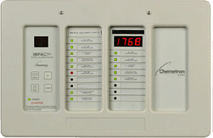
Allied IMPACT Local Alarm Panel


Features:

  • Accommodates any combination of 8-input transducer modules or 10-input switch modules.
  • Each transducer module can monitor any combination of pressure, temperature, flow, etc. inputs. 4-digit display cycles through inputs, displaying each reading in turn.
  • Primary power design accepts 115 or 230 VAC (50/60 Hz).
  • Communicates with PC-based alarm monitor software. (Software and Interface Module sold separately).
  • UL listed and ULC approved.
  • Patent pending.


Request a Quote specs-pdf


Description:
IMPACT® local alarm panels shall be designed to meet the requirements of NFPA and CSA standards. Alarms shall be UL listed and ULC approved as an assembly and shall include all necessary displays, factory wiring, transformers and circuitry requiring only 115 volt or 230 VAC primary power. Internal voltage shall be stepped down to 5 VDC and 15 VDC for control circuit power. Voltage to external pressure or vacuum transducers will be 15 VDC.


  • Local alarm panels shall be modular in design and accommodate a combination of 8-transducer modules (maximum of 3 8-transducer modules per alarm panel) and/or 10-input switch monitor modules. Each panel shall include a control module as standard, plus either 3 or 6 additional modules.
  • The control module shall include a Silence/Enter button, a Test/Shift button, an Up button, and a Down button. These buttons shall be used to silence the audible alarm, set up the alarm panel, and to test the alarm panel.The test button shall test all modules one at a time. An LED on the control module shall illuminate green to indicate power on.
  • 8-transducer modules shall include a 4-digit LED display and a vertical series of 8 LED’s, one for each input. The display shall cycle through each input in turn, indicating the reading of that transducer. The LED of the input being monitored shall flash to indicate it is the active display. In the event of an alarm, the input LED will change from green to red, and the audible alarm will sound. When silenced, the LED will remain red.
  • 10-signal switch input modules shall include a series of 10 LEDs, each monitoring a separate normally closed switch input. Each alarm signal shall be labeled for its function using self- adhesive labels provided with the unit. Adjacent to each signal label shall be a 3-color Light Emitting Diode (LED) to signify condition of the external switch. In the normal state (not in alarm) the LED shall be illuminated green. Activation of any switch will change the LED to red and activate the audible alarm. A “monitor only” state shall also be available. In this state, the LED will turn yellow when the remote switch opens, with no audible alarm.
  • The power supply shall be installed in the backbox. Power supply shall include a On/Off rocker switch and a fuse holder.
  • The audible alarm tone shall pulsate, 90 dBa at 2 meters. The audible signal shall be cancelled only by the alarm silence button or fault correction. The alarm shall automatically reset with the correction of the fault condition. Should a new alarm occur while the panel is silenced, the audible alarm shall reactivate. Regardless of the audible alarm, the display shall indicate abnormal as long as a fault condition exists.
  • The panel shall be equipped with contacts for connection to the PC-based alarm monitoring software. Alarms that require installation of additional circuit boards to allow PC-based monitoring are not acceptable.
  • Local alarm panels shall be Chemetron® IMPACT Series 74-15-XXX.